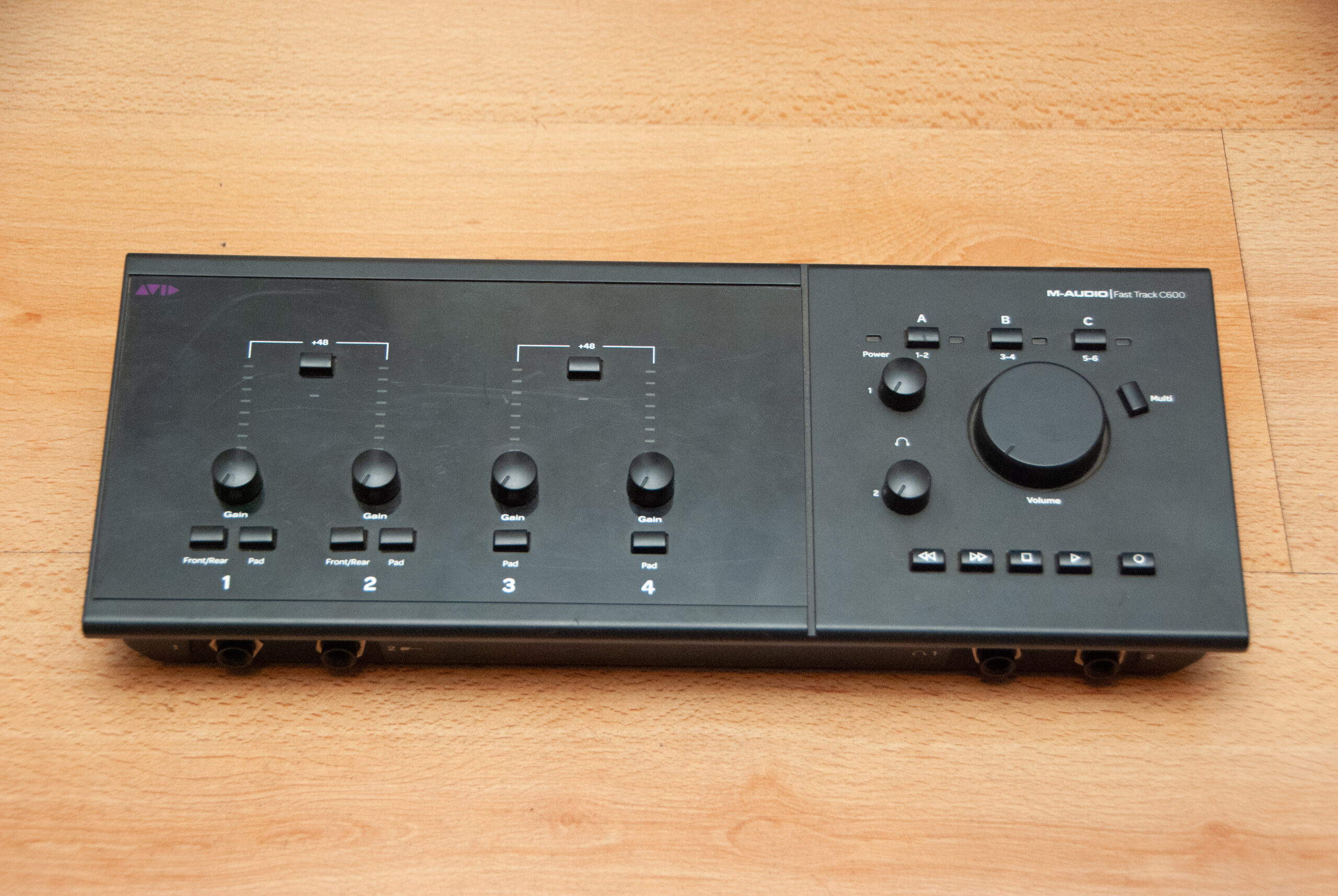
A few years ago, one of my high school music teachers came to me with a deal that was too difficult to pass up. He had just replaced his audio interface, and he wanted to get rid of the old one, which was of course faulty. Having known each other for a while, he knew that I was into that sort of thing and had decent chance of making it work. The device in question was a M-Audio Fast Track C600, a fantastic USB audio interface featuring 4 mic or line inputs with gain control, 6 balanced audio outputs, 96kHz 24bit crystal clear audio, low latency, and S/PDIF and MIDI I/O, along with many other tidbits and little details that make it a joy to use. It was way out of my price range, there was no way I could afford such a high-end device, and yet it was now mine. That was, of course, provided I could make it work in the first place. Today, we’ll delve into the adventure that was fixing it. Unfortunately, I didn’t take any pictures of the process, so you’ll have to take my word for this.
When I got home, I decided to plug it in and give it a shot, not expecting much. Instead of the usual greeting of flashing lights I was met with darkness. It was completely dead. My computer didn’t detect anything either, so clearly there was a hardware issue lurking inside. After opening it up, I was greeted with a myriad of cables routing lines back and forth from the two printed circuit boards that were inside, which looked pristine. No charring, no blown capacitors, no components rattling inside the case. the C600, or as the PCB ominously shouted at me (what I can only assume was the internal project name) in all caps, GOLDFINGER, looked as neat and tidy as the day it left the factory. A bummer it seemed. It wasn’t going to be an easy fix.
A breakthrough
And so it sat on my desk, half disassembled, for months. For one, I was still learning the basics of electronics, so there wasn’t much for me to do at that point. On the other hand, I was just getting into the world of digital sound, and my little Berhinger Xenyx 302USB was more than enough for what I was playing with back then.
Then one day, I decided to remove the lower board entirely (this is the one that holds all the important electronics, the upper one just has the display elements, knobs and buttons, along with the preamps for the inputs, which weren’t really necessary at this point), plugged the AC adapter (which I didn’t have, but an old 5V wall wart coming from an old Iomega Zip drive matched the jack and voltage perfectly) and the USB port, and started looking around the board.
At first, nothing really seemed to stand out, until after a while, when a smell of flux and solder caught my nose. For those who have never worked on electronics before, it’s a very pungent and characteristic smell, usually indicating a component that is way too hot. I started feeling around with my finger until I found the culprit; a tiny 10-lead MSOP package only slightly bigger than a grain of rice. I didn’t know what it was at first, but it had some big capacitors around, so I assumed it was some sort of voltage regulator, but the writing was tiny, and I couldn’t read the markings on the chip. After much squinting, I came to the conclusion that the markings read “LTABA”, which didn’t sound like a part name to me. A preliminary Google search came inconclusive, as expected, even after adding keywords and switching things around.
But then it dawned on me. a few weeks ago while hunting components on AliExpress, I noticed that most sellers usually wrote the complete markings of the chip on the listing, unlike other vendors like Mouser who just stick to the official part name. so I searched our magic word and lo and behold, there was my answer. Our mystery chip was, as expected, a regulator, the LTC3407 600mA dual synchronous switching voltage regulator from Analog Devices. The mystery was not complete however, as the regulator was of the adjustable type, and as such, I had absolutely no idea what voltages I was looking for.
But Goldfinger had me covered. etched on the silkscreen just a few mm away from the regulator, I saw three test pads, labeled “5V, 3V3, 1V8”. I assumed that the 5V was coming from either the USB socket or the AC adapter, while the 3.3V and 1.8V (voltages very common for powering digital microelectronics) were being handled by the dual-output regulator, stepped down from the 5V rail. After a quick continuity check, my assumptions were confirmed. The pieces were starting to come together.
A (not so) temporary fix
For a regulator to get that hot, usually one of two things need to happen. Either a short circuit on the output rail, or an internal fault that requires replacing of the chip. I discarded the short theory fairly quickly just by measuring the voltages. When a short occurs, the regulator usually switches off the output automatically and gives us a voltage very close or at 0V. In our case the output voltages were jumping around erratically, nowhere near the stated voltage on the board. While this was a relief in the sense that there was no problem with the board, it now posed an ever tougher question; what was causing this issue?
For a while I poured over the datasheet looking for an answer. At first I thought it was a problem in the feedback circuitry (the design of this circuit is what sets the output voltage and allows it to correct it as the load changes), but that would only affect one of the regulator subsystems, as each leg had a different feedback circuit. I also thought that the external components of the regulator (capacitors and inductors mostly) were faulty, but again, this didn’t explain why both rails were bust.
So I decided to quit. I’m not an electrical engineer (yet) and without a proper schematic of the board there was no way I could troubleshoot this PCB with my available tools in my house’s washing room. So I ripped the regulator out (It was slightly brutal, as this package has a massive solder pad beneath the package to dissipate heat, that is pretty much impossible to desolder amicably without a hot air rework station, which I don’t have) and went to my local electronics store and bought a 10-pack of LM317 linear adjustable voltage regulators. This million-year-old component, being a linear regulator, although trivially simple to install, has a massive disadvantage; unlike the original regulator which relied on switching the input voltage on and off really quickly, this one lowers the voltage by straight up dissipating the excess power as heat, which in turn means a greater power consumption. This meant both hoping that the USB port didn’t trip its overcurrent protection and adding heat sinks (salvaged from an old TV) inside the case with duct tape and wishing for the best. At least in my mind, this was all temporary. after soldering wires into the board, adding the passives for setting the voltage, and admiring my horrendous creation, we were ready for a test run.
First light, second problem
As I plugged it in, I saw das blinkenlights flashing at me for the first time. I was overjoyed when my computer recognized a new USB device. It was alive at last, but the battle was only halfway through.
For one, it turns out that Goldfinger doesn’t look kindly to USB hubs or USB 3.0 plugs. Both official and unofficial documentation warns the user to get away from both these apparent evils and stick to strictly USB 2.0. Luckily, my workhorse laptop does still include a USB 2.0 port which has given me no issues so far.
I had installed the “latest” (version 1.17, dated mid-2014) drivers available officially from the manufacturer’s website, which gave me issues since the beginning. Unstable on Windows Sound API, clicks and cutouts on ASIO, bluescreens if unplugged, bluescreens for no reason at all, poor hardware detection, you name it. After gouging through what’s left of the M-Audio forums, I found a post with the suggestion of rolling back to a previous version of the driver, which unfortunately went unanswered. So I gave it a try, downloading the 1.15 version (also available from the drivers site) and installing the old version. And at last, it worked.
A quick review, finally
So I’ve been using this interface for about a year now, give or take, and it has been a dream to work with. I’ve used it to record both live gigs and snippets and experiments of my own creation, and even used it a few times for livestreaming.
For me, it’s a perfectly adequate device for the kind of work I do, especially for free ninety nine. The user experience could use a tweak or two, especially the squishy knobs and the weirdly sensitive gain pots, but the build quality is solid, the connectors are a joy to use, and the included software is finicky, but powerful if you’re willing to respect it’s quirks.
Closing thoughts
While this turned out to be a massive project, both in time and scope, many important things were learned. First and foremost, never turn down free stuff, even if it’s broken. Turns out most people throw out things even if the fix is simple. Also, repairing things is good for the environment and usually cheaper than buying new. Second, just because the device you’re trying to fix uses some high-speed component doesn’t mean a 50-year-old component won’t replace it.
2 replies on “Fast Track C600: Faults and Fixes”
Great article, I have 2 of these M Audio C600 interfaces. One is working, and the sound is great, the other is not. Having read your article, I now think I should try fixing the other one. So, your article has been inspirational :))) all the best from Belgrade.
Wow, good job! I have been using a c600 for more than 10 years now with excellent recording results but varying driver stability results. Finally now it seems like the gain control on the second input preamp gave up. Might just get my meter out and try a bit of surgery after reading this, thanks for sharing!